Timing
You have probably looked at a log where the DME pulled 3° of timing and though that's not too bad then seen another log with 8° of timing pull and thought that's too much. Equally, you might have noticed that the ambient temperature is 110°F and intake temp 140°F and been unsurprised to see 6° correction. Why is this and how does the DME decide what the timing should be and whether to pull 0°, 3° or 12°?
Timing Overview
It is worth trying to understand in very general terms what the DME is doing. You probably already know that, to maximize performance, timing needs to be advanced upto but not past the knock limit. At the timing retard end, there is another limit called the combustion limit. This is the maximum retard that can be employed before partial burning and misfire problems start. One final quantity is the brake optimal timing angle. This is the angle that would achieve maximum possible torque (putting aside any fuel limitations). The DME is juggling these quantities depending on its aims.
- The combustion limit is useful for cat heating, sound tuning and antilag. Relatively little combustion energy goes into the pistons and most becomes heat, so the cat gets hot and unburnt fuel can be flushed into the exhaust.
- The optimal timing angle is used in torque calculations and torque intervention. The optimal angle provides for a reference torque that allows the DME to figure out the torque corresponding to the current timing it is running.
- The knock limit is the performance related number we all know and love. The DME employs a neural network approach to knock prediction, so it can estimate the probability of a knock event and use this to keep the timing safe but performant. In general, this allows the DME to avoid knock. If this fails and knock is detected, the DME will quickly drop to a very safe timing angle.
Basic timing angle
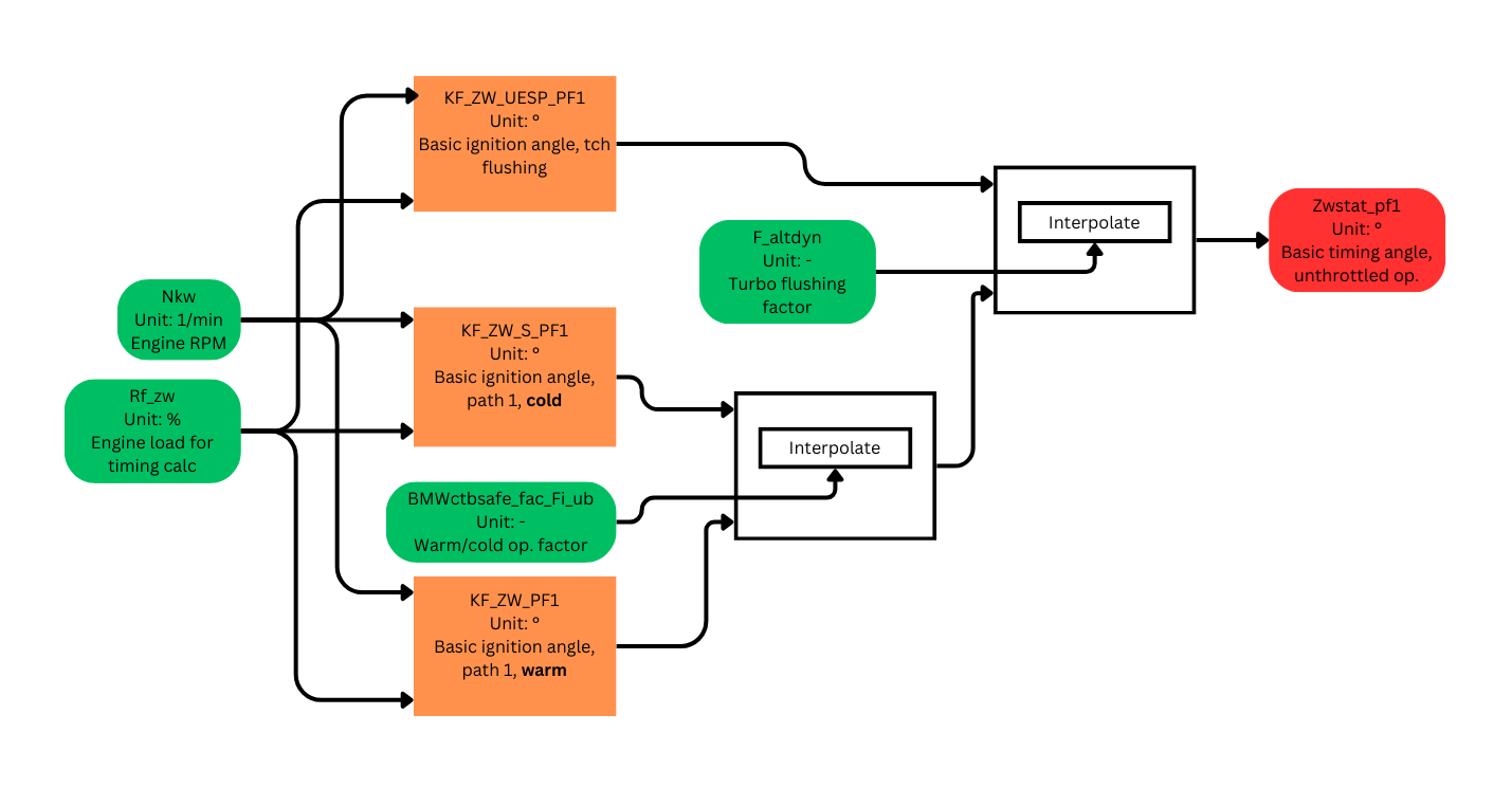
There are two main timing tables, KF_ZW_PF1 and KF_ZW_S_PF1.
Almost all timing calculations depend on the engine load (Rf_zwv) and RPM. The logic is that if RPM increases then the pistons are moving faster. If load increases the combustion flame front is moving slower. Timing calculations are attempting to marry up these two things. As RPM increases, timing advance increases. As load increases, timing advance decreases.
These knock-limited tables represent the timing advance you think you can achieve, with the best fuel for the tune without undue heat.
The KF_ZW_PF1 abbreviation refers to Kennfeld Zuendwinkel Path1 which translates as Map for timing path 1. The additional S means safe, although BMW comments use warm and cold.
In any case, the DME interpolates between the normal and safe timing maps according to its notion of engine readiness.
Path 1 is the normal operation path and path 2 is used for throttled operation. Path 2 is not shown but it is essentially equivalent in terms of logic.
Note the additional UESP maps which are used when turbo blowoff is being flushed through the engine. As you would expect, these are substantially retarted in relation to the knock limited maps. There is a blowoff factor, used for interpolation, which allows smooth transition between the normal and uesp maps on liftoff and gear shift.
The output is termed the basic, static ignition angle, zwstat. At this point, it is uncorrected.
Temperature corrections
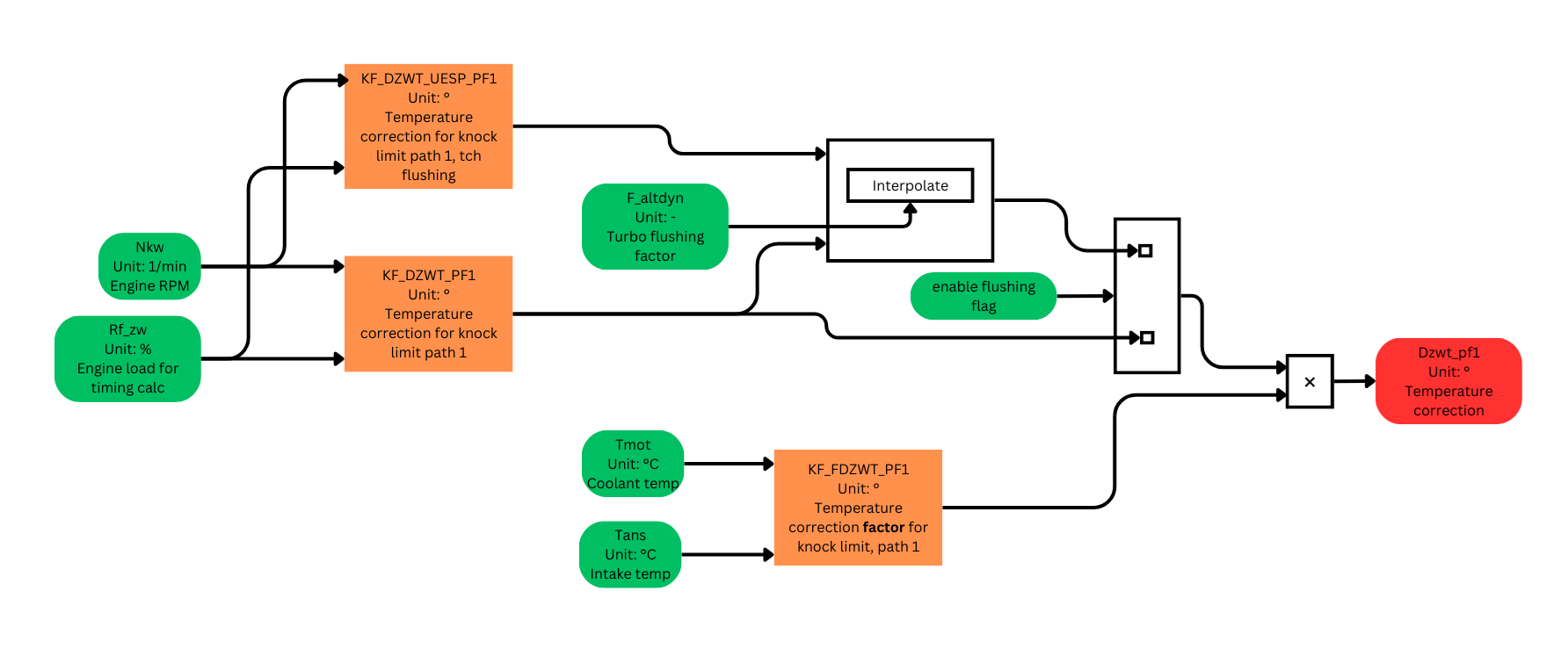
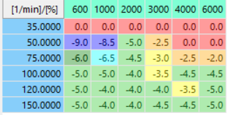
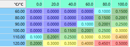
There are two parts to the timing correction 1. Calculate a timing mutiplier based on the temperature every second. This uses the engine and intake temperature, plus two tables, KF_FDZWT_PF1 and KF_FDZWT_PF2. Note that, because the temperatures are sampled once per second, timing logs often show a stepwise change in timing. 2. Apply it every 10ms. This applies three correction tables: KF_DZWT_PF1, KF_DZWT_PF2 and KF_DZWT_UESP_PF1. Can you guess what they are for?
The abbreviations are F for factor, DZW for delta Zuendwinkel (timing correction) and T for temperature.
As for the basic angle, the flushing table can be used with an interpolation.
Knock adaptation correction
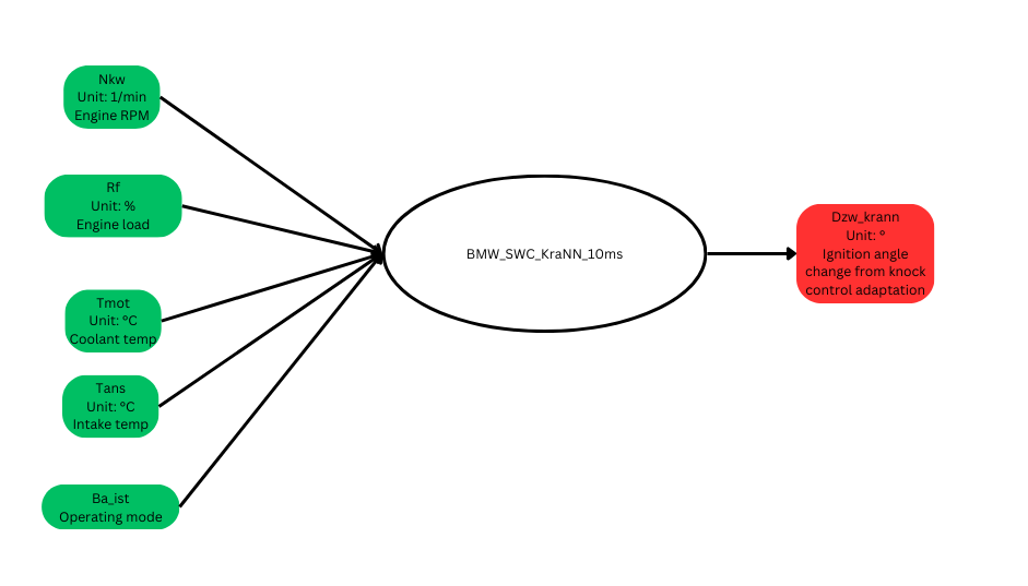
In this article, we will treat the knock adaptation as a black box and note only that it outputs another timing delta.
This parameter can be thought of as an octane correction.
Note that, if you are confident your fuel is good, and this value is adjusting timing, the basic angle tables are probably too aggressive. On the other hand, if your fuel is lower octant and this correction is zero, then the basic angles might be too conservative. Do not forget that this is all temperature, load and rpm dependent so both conditions can be true across the range of values.
Dynamic correction
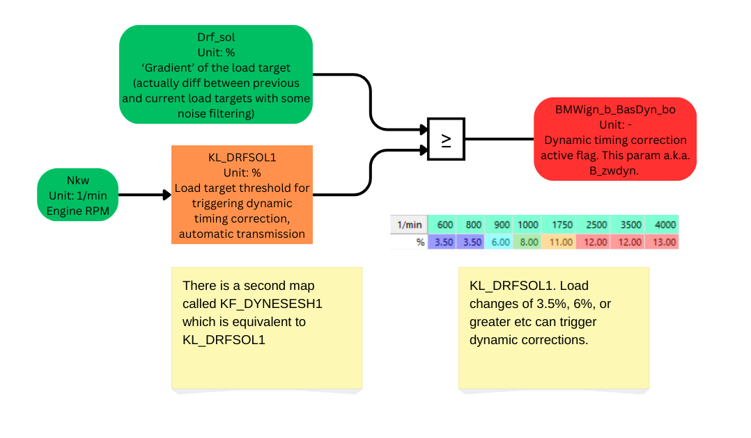
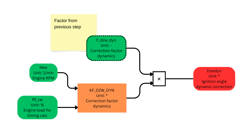
We can picture dynamic timing corrections as a blip in timing, applied when there is a sudden change in required load. Such a change might occur if the car is pulling away or at accelerator tip-in for example. The blip is a timing retard, which will reduce torque, but that the DME quickly ramps down to zero.
What might this achieve? Two side-effects would be
- a less jerky change in torque
- less chance of knock caused by doing the timing calculation using the wrong load value.
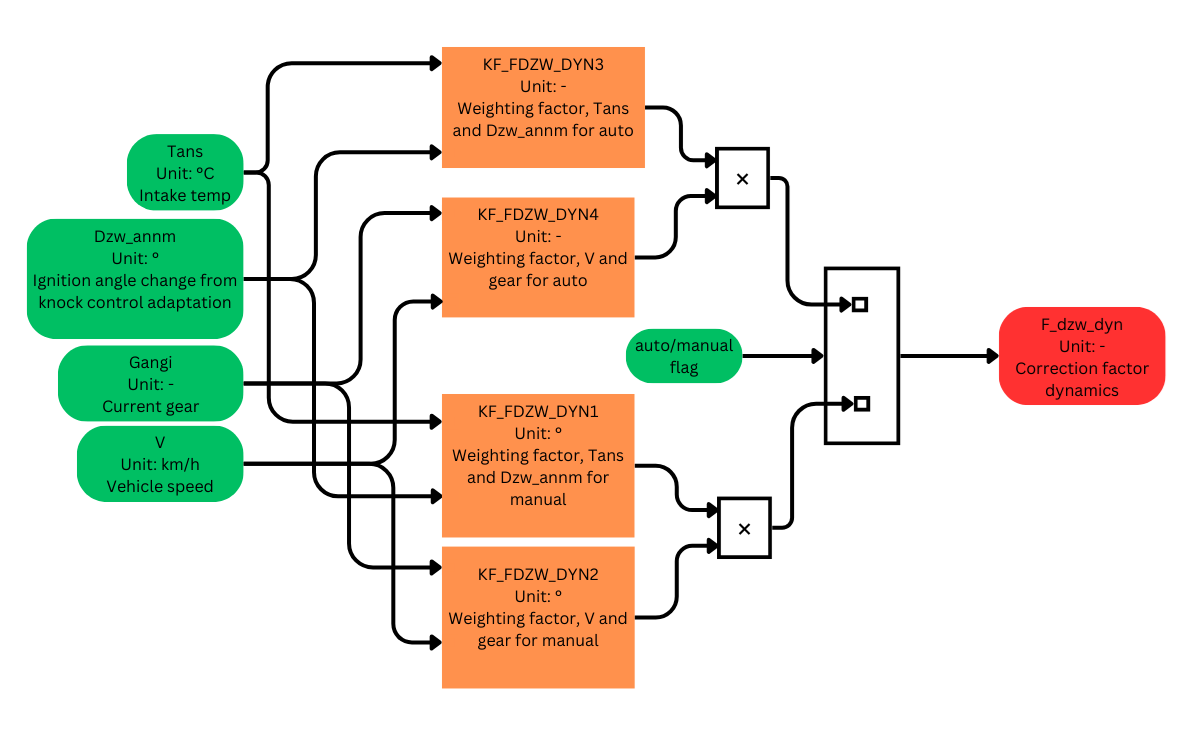
The DME's implementation of this feature is quite technical because the blip has to occur in a specific time window and has to be ramped out. We will ignore these aspects and concentrate on three essential steps: 1. Triggering. Is the change in load sudden enough to trigger dynamic corrections? The triggering step looks at the change in load target, compares this with a threshold value from KL_DRFSOL1. If the change is large enough, an enabling flag is set.
2. Calculation of correction factors. These are based on temperature, gear, the car's speed and any current timing corrections. There are four dynamic correction factor tables KF_FDZW_DYN1..4. KF_FDZW_DYN1 and KF_FDZW_DYN2 are for manual transmissions and KF_FDZW_DYN3 and KF_FDZW_DYN4 are for autos. Taking the auto case, KF_FDZW_DYN3 depends on intake temp and knock correction while KF_FDZW_DYN4 depends on gear and vehicle speed.
3. Lookup in the dynamic correction map, multiply by the factor and output the correction value. This is the essence of the calculation. A lot of complexity has been skipped over.
Lambda correction
Lambda corrections are zero on the gen 1. Lambda correction tables are not calibrated.
Application of timing corrections - corrected knock limited angle
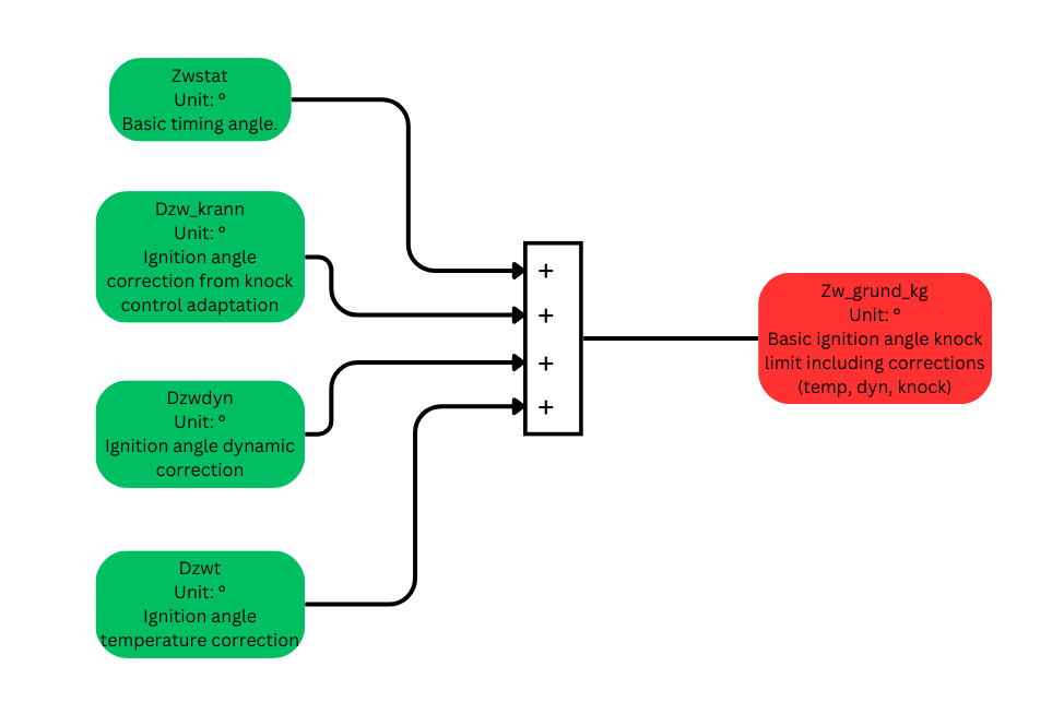
With corrections in hand, the DME adds together the basic angle and the corrections, to obtain the knock-limited angle. This is the timing angle that will be used unless the knock control or torque systems intervene.
Knock control intervention
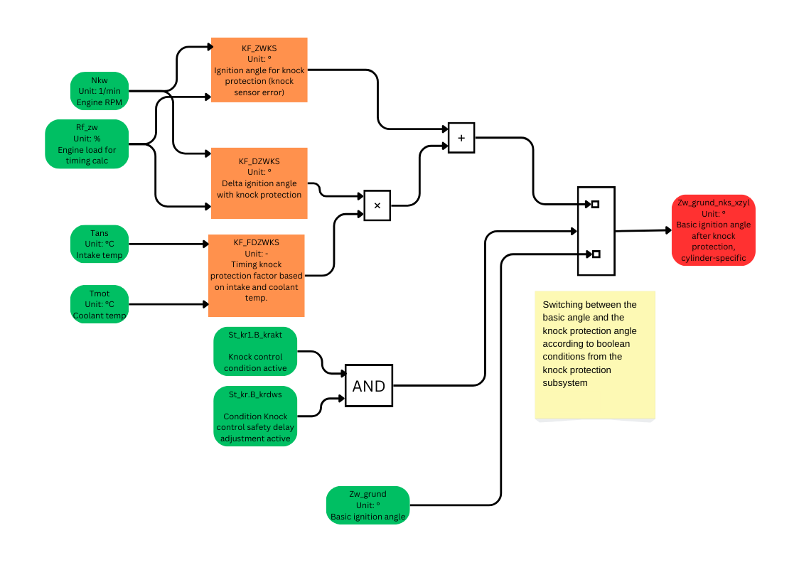
Here, the DME will discard the basic timing angle and revert to a very conservative retarded angle if knock is detected.
The maths is
We can see from the stock KF_ZWKS table that the knock angle is retarded for loads higher than 130%.
Furthermore, the temperature-based delta applies additional negative timing (i.e. retard) of about -2° after multiplication with the factor.
Torque intervention and optimal timing
The torque sub-system might intervene to specify a timing angle in order to reduce torque. This might happen because the gearbox or traction control asks for this or the car hits a load limit. This works by reference to a set of KF_ZWOPT_PF1, etc tables (not shown) which provide the torque-optimal timing and thus a reference from which the DME can determine some retard from this optimal angle to get the torque it wants.
In order to prevent too much retard from torque interventions, which might retard timing past the combustion limit, the DME has an additional set of minimum timing tables. If a torque intervention does specify an over-retarded timing value, the DME will discard it in favour of the minimum table value.
Zw_out: final timing angle
In addition to the basic, knock-limited angle, the torque angle and the knock intervention angle, there are other timing sub-systems, notably for startup and cat heating which are not shown, plus the DME needs to know which cylinder it is dealing with. The job of the IgnOut functions is to weigh up all these factors and provide a single, cylinder specific command to the ignition driver.
